
The River Thames at Reading passes over Caversham Weirs with a drop of about 1.4 m and an average year-round flow of about 37 m³/second. As at other weirs on the Thames, it seems a pity that all this potential energy is allowed to go to waste at a time when we are being encouraged to decarbonise and go green. With this in mind a community group, The Reading Sustainability Centre, made a proposal in 2014 to install a small hydroelectric power plant adjacent to the weirs and the lock. An initial feasibility study was commissioned, some surveys and investigations were undertaken, and an application was made for planning permission. As the project gained momentum it outgrew the original remit of the TRSC, and was handed over to a spin-off group Reading Hydro Community Benefit Society (“Reading Hydro CBS”), which has developed the project to its present stage of near complete design, planning acceptance, and procurement at the bidding stage. A preliminary design contract was let to the consultants Renewables First, who have developed the early design up to the present level of tender stage design, and have guided RH through planning procedures, permitting, and application for the Government feed-in tariff.
The project as it now stands comprises: –
- A twin-screw Archimedes turbine and generator sets installed in a concrete structure close to the northeast end of the Caversham weirs, linking the old mill stream upstream of the weirs, and the weir pool below the weirs.
- A natural fish pass linking the mill stream and the weir pool alongside the turbine structure.
- An electric cable connection from the generators to the Thames Lido, the main customer for the electricity to be generated. A connection will also be made to the SSE electricity grid for times when the Lido is off-line.
- Actuators and control equipment for automation of one of the 23 existing weir sluice gates. This will be operated in conjunction with the turbines, providing a compensation or balancing flow whenever the turbines are started up or closed down
Planning permission has been granted for a power plant comprising two Archimedes screw turbines together rated at 46 kW of usable power output, a total of around 300 Megawatt hours per year. The structure is located close to the northeast end of the main group of gated weirs, cutting through a causeway which links the weirs to View Island and beyond, to lower Caversham. The causeway carries a busy public footpath which will have to be diverted during construction and reinstated on completion. The turbine screws will each be of diameter 2.6m and will take a combined flow of 6.2m3/s at a nominal head drop of 1.4m. The screws are mounted in a semi- circular trough at an inclination of 22 degrees to the horizontal, and sit on bearings at each end. Each turbine has a total spindle length of 6.6m and a bladed length of 3.6m, having three individual flights (blades) making three complete helical turns. At the upper end a generator is driven via a gearbox. The turbines are mounted in a concrete structure which includes an intake channel drawing from the Mill Stream close to the upstream side of the weirs, debris screens, a public footbridge, penstock gates, two parallel steel-lined concrete semi-circular troughs to house the turbine screws, and an outfall channel discharging to the weir pool below the weirs. The generators will sit inside a small house, along with all electrical switch gear and control panels. The exact design of the house is yet to be determined, but it will have a pitched roof and (possibly) brick walls, subject to approval by the planning department.
The greater part of the main concrete structure will sit off to the side of the causeway, within the Weir pool.
The Turbines and Turbine Structure
It will be constructed inside a sheet piled cofferdam, which will be partly removed with the underground piles incorporated into the permanent structure. Apart from where the intake channel crosses the causeway, there is not expected to be a great deal of excavation as the floor of the structure is more or less at the present bed level of the weir pool.
All the mechanical and electrical equipment, including the screws and their associated troughs are currently being designed in detail and will be supplied and installed by the company Spaans Babcock. The concrete works, the piling, and all the temporary works are bundled into a civil works package, yet to be awarded but currently being bid by two contractors, Mackleys and Land & Water.
Figure 2 shows a diagram of a similar Archimedes screw turbine.
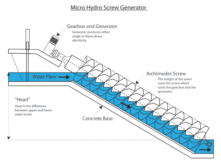
An excellent video of a typical installation can be seen here:
Ancillaries at the Turbine Structure
The inlet to the power plant includes coarse screens to catch floating debris and prevent it entering the turbines. It is only intended to intercept large objects such as tree branches, boats, or man- made debris such as fenders, barrels, or sheet materials. Fish, weeds, and soft vegetation can quite safely pass through the screws without damage either to themselves or to the turbines. During operation the screens need to be inspected daily, and raked clean as necessary. This is a manual operation which could be assigned to volunteers in the long run. The inlet channel cuts across the existing causeway which currently serves a public footpath linking. Reading to Caversham via the lock and the weirs. A simple slab footbridge will form the roof of the inlet channel, and will be provided with handrails and serve to reinstate the footpath after construction.
Also in the inlet channel there are penstock control sluice gates, one for each turbine. These are set just inside the turbine house, and because they rise vertically their headstock frames set a lower limit on the ceiling level internally. The gates will be operated automatically by the operating logic for the plant.
The turbine house itself sits over the top end of the turbine shafts and the associated gearboxes and generators. This is the only part of the structure that stands above footpath level, but it is located immediately to the side of the footpath and on top of the main turbine structure. At the end of the inlet channel the twin Archimedes screw turbines sit in parallel semi-circular troughs inclined at an angle of 22 degrees to the horizontal. The steel liners of the troughs will be provided by the M&E contractor along with the screws themselves, but after placement and adjustment into precise position, the liners will be cast into second stage concrete for rigidity.
The Fish Pass
A requirement imposed by the Environment Agency on all development works at weirs or locks on the River Thames is the inclusion of an associated fish pass to facilitate upstream passage of migrating fish. Most weirs including Caversham already incorporate a fish pass of the Larinier type (a steel trough with baffles), but these are only suitable for fast moving fish of the salmonid family (salmon, trout, char, grayling). The EA are keen to open up the whole river to migratory coarse fish and in particular to eels.
A fish pass for these less agile fish species has to have a slower flow, and lots of resting pools. In our case we will adopt part of an existing former flood channel as a “natural” fishpass channel, tying it in at the upstream end to the Mill Stream via a short culvert under the footpath and a short concrete channel with baffles and artificial reeds. At the downstream end it will terminate at a narrow throat adjacent to the turbine outfall, shaped and sized in such a way as to locally accelerate the flow to a velocity higher than the turbine outflow, so as to provide an attraction flow that the fish can sense and follow. The main length of the fishpass channel will be formed by adoption of an 80m length of the existing meandering ditch, simply by regrading it to a gentle slope, and placing stones or old tree trunks to form a series of riffles and pools. It will remain earth lined and with natural vegetation left in place.
The fish pass is designed to convey a flow volume of 0.6 m3/s. For most of its length the width varies between about 3m and 6m, and velocity will be low, but at the downstream end (confusingly referred to as the fishpass entrance (from the point of view of the migrating fishes)) the velocity will accelerate to about 2.0 m/s through the “throat” located co-terminously with the turbine outfall. This is achieved by narrowing the channel to 0.6m wide and profiling the floor to the shape of a Crump weir with special “eel tiles” on the crest. At the upstream end the concreted channel of length about 15m connects to the Mill Stream at a shallow culvert serving as a bridge for the public footpath. The hydraulic width will be about 3m, and there will be provision for stoplogs to shut off the flow when required. Special brush furnished piles with artificial bristles will be provided to assist eels to wriggle their way against the flow.
Electrical Connections
The M&E contractors are responsible for wiring up the generators, switch gear and control panels, but separate provision has to be made for making an electrical connection from the power plant to the consumers.
An arrangement has been made with the owners of the nearby Thames Lido, a recently restored early Edwardian swimming pool, fitness club and restaurant, for them to buy most of the electricity generated by the Reading Hydro project. The pool is electrically heated, and their 24 hour – seven day a week electricity consumption is a near match to the predicted output of the hydro project. However, there will still be a need to maintain a supply connection to the SSE network grid for times when the hydro plant is out of service. Similarly the hydro scheme will need to make a connection to the SSE grid for times when the Lido is not operating. The Lido is the opposite side of the River Thames from the Hydro plant, with the full width of the weirs, the lock, and Lock Island in between. The direct distance is about 150m. There are three possibilities for making a cable connection to the Lido. The first is to lay a cable in existing ducting across the weirs, to an existing network connection on Lock Island. From this point to the Lido itself power would be transmitted through the existing SSE grid, which would necessitate an arrangement with the suppliers. The second configuration would be to cross the weirs in the same way, but then to continue with the same cable threaded through an existing duct under the bed of the lock cut to a connection point at the Lido itself. In engineering terms both of these alternatives are relatively straightforward, but wayleaves have to be negotiated with the EA as owners of the weirs and lock, and they have intimated that this may be quite expensive.
The third alternative is to engage a specialist contractor to install a duct and cable by HDD techniques (horizontal directional drilling), drilling straight under the river from the power plant to the electrical services bay at the Thames Lido, where direct connections would be made to both the Lido and the SSE grid. This provides a simple solution but has an associated cost. The solution to be adopted has yet to be decided.
Compensation Weir Gate Control
When the turbines are started up or shut down, this changes the local rate of flow in the river, and in order for normal navigation and flood control is to be maintained a compensatory adjustment has to be made in the degree of opening of the control gates at the adjacent weir. Normally it is a requirement for a hydroelectric power plant to be fitted with a gated bypass channel to provide a compensation flow in this way, with a control system linked to the generator controls and programmed to automatically open the gate when the turbines shut down, and vice versa, to close the gate as the turbines are started up. In this way the operators responsible for the overall control of the river (the Environment Agency) can be assured that the flows upstream and downstream of
the power plant are kept in balance, and there won’t be a sudden uncontrolled surge in flow affecting the river levels and the settings of the main bank of weir gates.
In our case the EA have made an exception which will save us the cost of constructing a bypass channel. The main group of weirs at Caversham has 23 individual gate openings, each fitted with either a radial or a sluice gate, all of which are motor operated, but only some of which are remotely actuated. The EA have agreed to assign one of their gates to operate conjunctively with the hydro plant, provided we fit it out with remote actuation and link it in to the generator control logic. The EA have their own weir gate control system, not just for Caversham weirs but for all the groups of weirs, level recorders and flow gauges on the whole length of the river. As primary operators of the river with responsibility for navigation and flood control, they have to have total sight of all activities that affect the river conditions, and accordingly they must have sight of the operating status of the hydropower plant at any given moment. They must also have ultimate control in case of emergency, so it is a requirement that the Reading Hydro control system is linked in to the EA’s operating system, while at the same time providing safeguards to prevent RH’s system from affecting any of the EA’s equipment. The control system and programmable logic controller (PLC) for RH will be supplied and set up by the M&E contractor (Spaans Babcock), but the exact specification has yet to be established. It is RH’s intention that live data such as instantaneous power output, turbine status, and upstream and downstream water levels will not only be displayed and recorded at the control panel, but will also be accessible on line, and relayed to a public information display panel outside the turbine house and visible from the public footpath.

Operating Philosophy
The power output of the turbines is a function of the available flow and the head drop between the upstream and the downstream water levels. The design of these turbines is based on a head drop of 1.4m and a flow for each turbine of 3.1 m3/s. They can operate at a limited range of flows and available head around those values, albeit with correspondingly varied power output. However, when the available head or flow is insufficient, the turbines will have to be successively shut down.
The average year-round flow in the River Thames as measured at Reading Bridge is 37m3/s. However, this varies between single figure flow rates in dry summers, and flood flows of 180m3/s last December, and well over 200m3/s in recent winters. In managing the river flows, the EA have an operational hierarchy of priorities for water use, and these include an allocation of flow for the lock operation, a “sweetening” flow along the Mill Stream to maintain water quality and limit sedimentation, flows at the existing and (our) future fish passes, flows for our power turbines, and finally any remaining flows though the various gated weirs. The turbines will only be allowed to operate while there is sufficient flow available within those criteria. According to historic records the turbines would have to be shut down because of insufficient flow for about 12% of the time, mainly during summer months.
The turbine operation also depends on the available head drop between upstream and downstream water levels. The upstream water level is generally maintained at a fairly constant level, held there by the EA’s operating system which opens or closes weir gates according to the flow conditions. There are occasions, however, when the upstream level is deliberately drawn down, for example in anticipation of an oncoming flood in order to free up storage volume above normal water level. Conversely there are times such as during high flooding when the upstream level inevitably rises. By contrast, there is a much greater range of water levels downstream of the weirs. This is because the downstream level is controlled from the weirs at Sonning, some 4.3km downstream. As the flow in the river increases, so the hydraulic gradient increases and the water level below Caversham weirs rises, decreasing the available head drop at the turbines. In other words, and perhaps counterintuitively, the greater the flow in the river, the lower the available head and the lower the potential power output of the turbines. Analysis of historic data shows that we expect to have to shut down turbine operation for this reason for a further 12% of the time, mainly in the winter months. Overall, we expect to be able to operate the power plant for about 75% of the time, with shutdown periods due to insufficient flows and insufficient heads in about equal durations. This percentage duty factor has been taken into account in working up the economic case for the Reading Hydro project.